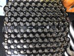
Replacing bad battery cells


Cyrus David

Active member
Likes
25
Location
West palm beach
I’m working with Cody, a local guy who also has an Alta and may end up attempting some cell replacements on his batt soon (his bike is in my garage and has a pack fault which won’t allow above 50% charge).
If I make any headway i’ll Post about it. I’m not a software guy but have spotwelded lithium cells in the past with my home made spot welder.

I am sure you guys are aware, but I will post it anyway.
What you guys are planning to do is extremely dangerous without the proper equipment and training. Please be very careful.
 

snydes

Moderator
Staff member
Likes
2,796
Location
Pennsylvania
Have been in these packs a few times and I can say it will take some engineering. The electronics on the chassis side are fully dependent on the electronics inside the battery.
The controller is looking at all kinds of data from the pack:
*Total HV
*12vdc output (handled by the step down converter inside the battery)
*Pack temps
*Cell balance
*pos&neg main contactor control and status
And these are just to name a few.
The battery is more of a smart pack..
The software and design guys would need to do a redesign of large scope to fit a different batt to the Alta.
I’m working with Cody, a local guy who also has an Alta and may end up attempting some cell replacements on his batt soon (his bike is in my garage and has a pack fault which won’t allow above 50% charge).
If I make any headway i’ll Post about it. I’m not a software guy but have spotwelded lithium cells in the past with my home made spot welder.

It sounds like Cody found the right guy to help him. I sold Cody his charger and was trying to help him figure out what was going on with that bike but it wasn't looking promising.

The problem with cell replacement is those cells are epoxied into the module housing, so any attempt to replace cells is going to require a destructive disassembly of the module. There are now a few module housings coming out as a result of the final smash and grab of the Alta facility, whether those parts make it into the hands of friendly members of this community wanting to help it or those looking to exploit it is anyone's guess. At any rate all the wirebonds will have to be destroyed to get the circuit board off, so a reasonable solution to creating new fuse wire connections has to be established. The Alta fuse wire is some sort of 24 AWG aluminum that was probably spec'd out by the manufacturer of their wirebonder. For a spot welding process I think our only option would be tinned copper, so we would have to determine what size tinned copper would come close to the "blow" characteristics of the aluminum fuse wire. I suspect that even then the resulting fuse will be less than ideal compared to the engineered Alta product, but if it's that or a pusher bike, than I suspect we will have to deal with a compromise.

Cyrus David, you have some very good information to contribute to the ongoing research project about these Alta batteries, I suggest we move this discussion into a more appropriate spot where we can keep it going and make it easier to find in the future. Perhaps @Philip can juggle that around for us?

Thank you
 

Cyrus David

Active member
Likes
25
Location
West palm beach
Yes, i’m Thinking that I may have a creative way to replace a bonded cell. I also saw recently posted a few internal batt parts (with no cells) that I may try to get my hands on when I get some money free. I’m not going to be able to duplicate any “fuseable” links so likely any individual cells I replace, may be un protected with a tin strap for bonding. I’m creative and a licensed Jet Mechanic for 20years so I have some resources outside my garage but bottom line it’s worth a try.. has anyone heard of any persons getting rid of a bad battery? I could use it for my experiment.

9FA44378-DDA0-4200-90D1-18243FE00D21.jpeg
 

snydes

Moderator
Staff member
Likes
2,796
Location
Pennsylvania
There are many DIY guys that have successfully spot welded tinned copper wire, so that is certainly an option. There is also a good bit of information out there as to what size wire will withstand what amperage. The trick is finding that size that best performs like the 24 AWG aluminum. The problem also is the amount of room we have to work with on the negative connection, that's really the challenge. I was hoping one of those module "honeycombs" would fall into our hands so we could blueprint and reproduce it. @TCMB371 would that be something that could be reproduced by 3D printing or is it too big? Either way I'm sure it would be a wildly long print time, but what we need are reasonable solutions that can be done on a small scale, so maybe it is our best reasonable option.

There are some bad A packs out there, but the people with them are holding on to them as far as I know. For the last several months I've been working with @Bloak , he and I have "code 36" R packs. We've been trying to find another R pack to harvest modules to repair our batteries, if we ever do, we will potentially have a leftover pack full of code 36 modules that could be used to experiment on. Until then we have to work with what we got, which isn't much.
 

Mark911

Well-known member
Likes
1,123
Location
Corona Ca
There's probably three or four of us out in Alta land working on a cell replacement process with the common theme being we're all looking for bad modules to experiment with. Of course, if the battery is bad enough that it'll only charge 50% you've got almost nothing to lose.

My approach would be to map out the bad cells and using a counterbore with a mechanical stop carefully cut the bottom plate to expose the negative end of the cell. There'll be some cured film adhesive (blue) between the two so you'll get some warning before you go too far. Then snip the fuse wires and push the bad cell(s) out through the bottom.
Pre weld the +/- leads to the new cell(s) and balance the new cell(s) to match the module. Align and position the new cell(s) into the corresponding bores and finalize the terminations to the PCB however you desire. Do whatever electrical tests you think is appropriate at this stage.

Using a hole saw with no pilot, cut out preplacement "disks" for the bottom plate. Here's the first big unknown, what did Alta use to bond the cells to the plate? Not sure, but I guess some kind of thermally conductive electrically insulating pressure sensitive room cure film adhesive. There's quite a few choices in the aerospace industry so take your pick and cross your fingers. Select the proper thickness film adhesive and bond the "disks" over the negative cell ends using a flat plate to ensure co-planarity of the bottom plate interface surface.

Final electrical test and re-assembly into pack. That's it!
 

snydes

Moderator
Staff member
Likes
2,796
Location
Pennsylvania
@Cyrus David , are you considering a complete or partial cell replacement in a module? The reason I ask if you are considering only replacing some cells that say aren't taking a charge, I believe you are still going to end up with imbalance issues since the rest of those cells in the module likely took a hit in capacity from the under discharge condition. If you were successful in replacing one parallel group with new cells (should that be possible), that group will have a different capacity than the rest most likely resulting in the bike thowing an imbalance fault code.
 

Cyrus David

Active member
Likes
25
Location
West palm beach
@Cyrus David , are you considering a complete or partial cell replacement in a module? The reason I ask if you are considering only replacing some cells that say aren't taking a charge, I believe you are still going to end up with imbalance issues since the rest of those cells in the module likely took a hit in capacity from the under discharge condition. If you were successful in replacing one parallel group with new cells (should that be possible), that group will have a different capacity than the rest most likely resulting in the bike thowing an imbalance fault code.

I’m going back into @Cody129 battery and going to meter and chart out all 4 modules to determine how many are driving his imbalance that is throwing the fault. When I “hand balanced the pack I had every cell within .1v and every parallel group within .2-.3v. I thought that would be sufficient but then after I reassembled the pack and charged it with my new handy-dandy HV regulated power supply they must have taken further charge at different rates. The last of the charging had to be done in the bike w the Alta charger. So without going back inside I can’t tell what group drifted or hit a premature charge threshold. I can also go straight to a lazy cell and wake it up sometimes with a little amperage but won’t know that until tear down..
My idea is actually to mount the cell upside down and have a conductor follow in the bore along the side of the battery. This space would be filled by the epoxy also.
Boring done with a vertical end mill and obviously have an accurate depth measurement. I understand the balance problem but with a new cell but i’m Trying to see how the balance sampling is actually done before I pose this as a big problem. I’ve got some more testing to do to see at what arrangement the cells are sampled exactly.. ohhh to have a wiring diagram of this damn thing. I’m making a lot of assumptions with the little I know about the batt design.
 

snydes

Moderator
Staff member
Likes
2,796
Location
Pennsylvania
This is why we need to have a guinea pig module. I fear there is epoxy along side the cells as well as the bottom, so even if we were able to cut a precision hole in the bottom it's still likely going to be a monumental task getting the cell out. I hope I'm wrong on that. Keep tabs on this latest development with the Alta Multi-Tool software. Check out this picture of the battery graph HERE. It looks like we will be able to accurately find his problem area without having to test every cell in every module.
 

Cyrus David

Active member
Likes
25
Location
West palm beach
Wow nice software! That’ll save some time.. I have been doing it the hard way and after reading some of those threads I would have brought the parallel groups much closer..
 

Mark911

Well-known member
Likes
1,123
Location
Corona Ca
Based on some of the screen shots from Alta West I'd say you'd need to be within .005v on the parallel group and .05v at the module level for the system to pick up the remaining balance task. That means using a precision (lab grade) power supply capable of regulating current and voltage down to that level. I used an HP6634B to do my module level charging but would need a HP6632B to do any cell level charging.
 

Cyrus David

Active member
Likes
25
Location
West palm beach
This is why we need to have a guinea pig module. I fear there is epoxy along side the cells as well as the bottom, so even if we were able to cut a precision hole in the bottom it's still likely going to be a monumental task getting the cell out. I hope I'm wrong on that. Keep tabs on this latest development with the Alta Multi-Tool software. Check out this picture of the battery graph HERE. It looks like we will be able to accurately find his problem area without having to test every cell in every module.

Does anybody have this tool in FLorida?
 

OneLapper

"You don't *really* need the water pump...."
Forum's Sponsor
Likes
989
Location
Connecticut
Does anybody have this tool in FLorida?

You can now down Alta Mulitool software. Someone anonymously posted a link to download it.

That said, it appears that it's pretty involved to get up and running. You need Ubuntu, USBCAN adapter, and the bike side cable.
 

Mark911

Well-known member
Likes
1,123
Location
Corona Ca
My recommendation, other than the obvious precautions regarding DEATH when working with high voltage, is to work on a bench equipped with wheels in an area with outside access. That way, if a cell decides to go thermal you can get the pack/module outside quickly where any resulting fire wont cause additional harm. You don't want to risk burning your house down just to get your bike running. Also, if you must move individual modules about do so on a non-conductive cart. You don't want to get a little "tingle" from 84v causing you to drop the module, which besides the obvious damage could start a fire as well. Keep the protective covers on whenever it's not absolutely necessary to have the PCB exposed.
 

Similar threads

Top Bottom